
The point of the Lumos project is to provide computerized control of devices. The software suite handles the orchestration of the devices, timing them to music, or even fully custom solutions build on the Lumos framework. None of that can do much without an interface between the computer and the devices being controlled.
There are a number of such devices which may be used. Commercial X-10 devices are available (but aren't usually the best suited for high-precision or rapidly-changing device control). Electronics hobbyists may build or obtain various Do-It-Yourself controller units popular in the DIY Christmas lighting community, such as the Olsen, Renard, Firegod, and others.
The Lumos project also has a line of DIY controller circuits intended for the experienced electronics hobbyist who wishes to experiment with computerized device control. These are open-source hardware projects, meaning that all the necessary plans, source code, and instructions are available here free of charge for you to build a similar device yourself. This information is provided in the spirit of Open Source, and under the terms and conditions of the Open Software License. You may use and redistribute these materials with credit given for their source(s). See the project documentation for full licensing details.
Please understand that these are plans for building electronic circuits which control electrical power. If you undertake to build one, you do so entirely at your own risk and are liable for any and all consequences of doing so. It is assumed that you know how to build and operate such circuits safely. These plans are offered for educational and experimental use on an "AS-IS" basis. They are not consumer-ready commercial products.
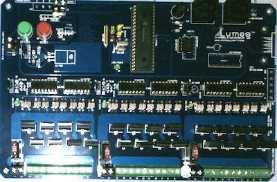
This is an all-in-one controller and relay board. The controlling PC sends commands to the board via serial interface. The output channels are grouped into three blocks of eight channels, each block fused and isolated from one another and from the board's internal logic circuits, allowing each block to control devices of different voltages. Each block has a maximum capacity of 10 amps, 24 volts DC. Absolute maximum output on any single channel is 5 amps. (These should be considered absolute maximum peak levels; the relays are designed to operate at sustained levels less than that.)
The following optional configuraitons may be selected at the time the board is assembled:
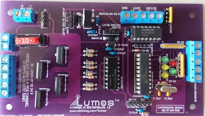
This is a scaled-down version of the 24-Channel DC Controller/Relay. It provides four DC output channels and up to four sensor inputs. It may be controlled by full- or half-duplex RS-485, hard-wired to the board's terminal block. Built-in RS-485 termination socket. May be built as a relay-only configuration, taking four TTL-level logic inputs to drive the DC outputs rather than on-board intelligent control.
This project is under development and will be released later in 2014.
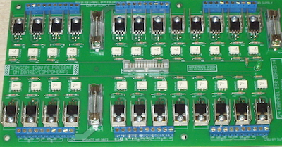
Relay-only board. Takes 24 TTL-level logic inputs which control 24 solid-state relays, arranged in three isolated blocks of eight channels. Each block has a maximum capacity of 8 amps, 120 volts AC. Absolute maximum output on any single channel is 5 amps. (These should be considered absolute maximum peak levels; the relays are designed to operate at sustained levels less than that.)
This project has been experimentally built and used successfully by the author. It is not offered yet as a DIY project, but may be in the future.
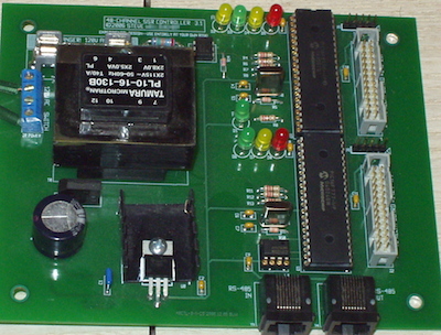
A 48-channel controller only, including integrated power supply (120 volt power input) with AC zero-crossing detection circuitry necessary for control of AC relay boards. Designed to drive two 24-channel relay boards (AC or DC).
This project has been experimentally built and used successfully by the author. It is not offered yet as a DIY project, but may be in the future.
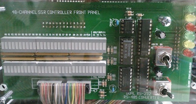
This board provides a front panel for the 48-channel controller, with LEDs indicating the status of output channels.
This project has been experimentally built and used successfully by the author. It is not offered yet as a DIY project, but may be in the future.
We crowdsourced the construction of a set of final prototype Lumos DC controllers to work out the details of the design before being able to say that it was complete. Thanks to all those who contributed to make this effort possible:
| Fan Level | |
| Amanda Allen | |
| Supporter Level | |
| Carey Adams | Sue Allen |
| Andrej Čibej | Betsy Fernley |
| Beth Gordon | Sara Jacobson |
| Tanya Spackman | |
| Backer Level | DC |
| Silver Level | |
| David Johnston | Melf |
| Gold Level | |
| Rob Beasley | Phil Willoughby |
| Patron Level | |
| Casey A. | William H. Ayers |
| Jon and Rebecca Garver | Andy Kitzke |
| Joseph Moss | Robert A. Nesius |
| Patrick Quinn-Graham | Jama Scaggs |
| Doug Van Camp | Matthew Wentworth |
We also wish to thank Darren Bliss who has been a great supporter of the Lumos project since the very first prototype was being experimented with, and the other Kickstarter backers and friends who offered moral support, other levels of contribution, or who wished to contribute anonymously.